
Overview
Light Fields
In 1846, Michael Faraday, an English scientist who is well known for his contribution on electromagnetism, proposed that light should be interpreted as a field, much like the magnetic fields on which he had been working for several years. The term “Light Field” was coined in 1936 by Andrey Gershun, a Russian physicist, in a classic paper on the radiometric properties of light in three-dimensional space (Wikipedia). The definition of light field can be convoluted, but in simple terms can be understood as the total of all light rays in 3D space, flowing through every point and in every direction.
 Simulated Ligthfield. |
Once light is radiated by a source like the sun or any lamp, it travels through space in straight line (assuming no external influence). When light reaches and hit any surface, part of it is partly absorbed, and partly reflected or refracted (when entering a different medium) and continues to travel until it bounces off again. We say it light “illuminates” our surroundings when the light reflected by all objects around us reach our eyes. Our visual field naturally depends on our position within the light field at a given time. By moving around, we can perceive a different part of the light field, thus we get a sense of our location and location of object around us. In more technical terms, light rays are described by the 5D plenoptic function which can be described as follows: Each ray is defined by three coordinates in 3D space and two angles to specify their direction in 3D space. For more information on light fields, you can visit the LightField Forum and the Stanford Light Field Archive.
 Plenoptic Function (from class slides) |
Capturing light fields.
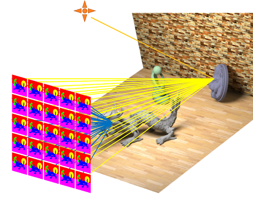
Since the conception of the camera obscura, people have been interested in recording light as a mean to capture a snapshot of time. Capturing techniques have been improved for decades and the include either electronically by means of an image sensor, or chemically by means of a light-sensitive material such as photographic film. A common camera (either digital or analogous) only captures a flat, two-dimensional representation of the light rays reaching the lens at a given position, at a given time. Electronic 2D sensors record the sum of brightness and color of all light rays arriving at each individual pixel. However, a light field camera (technically, a plenoptic camera), not only records brightness and color values in the 2D imaging sensor, but it is capable of recording the angle and direction of all the light rays arriving at the sensor. This additional information can be used to reconstruct a three-dimensional model (or 3D maps) of the captured scene by calculating the origin of each light ray that reached the camera. Creating a system to capture light field is not an arbitrary task as it requires a solution that can capture light from a scene from multiple locations. Some common ways to capture light fields are:
- Using a single, robotically controlled camera.
- Using a rotating arc of cameras like Google 6-DoF VR light field camera rig.
- An array of cameras or camera modules like the Stanford Light Field Camera array.
- A single camera or camera lens fitted with a microlens array like Lytro Camera.
 Google 6-DoF VR light field camera rig |
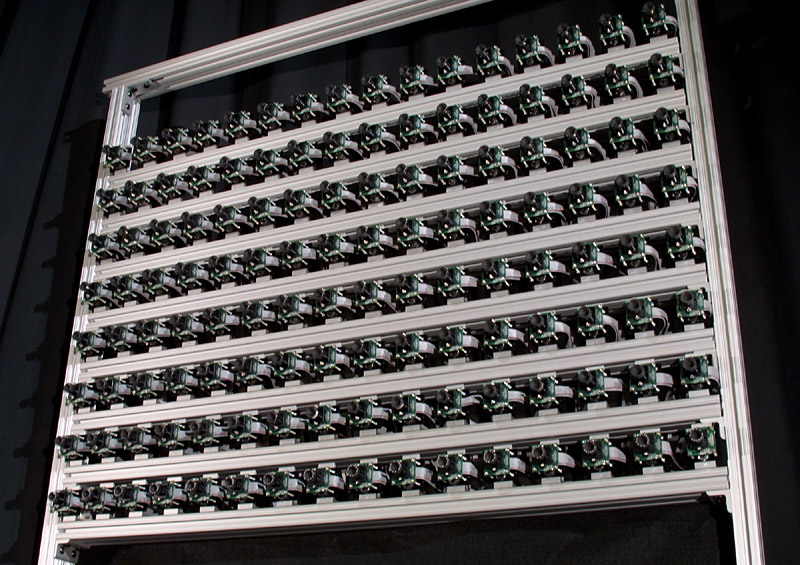 Stanford Light Field Camera array |
Lytro Camera: The first consumer Plenoptic camera
Ren Ng a Professor at Berkeley founded Lytro, a startup that designed the first light field consumer camera. The Lytro Camera, as it is called, is able to store information separately about all the rays of light entering the lens, from different distances and angles by using a microlens array between the sensor and main lens, creating a plenoptic camera. Each microlens measures the total amount of light deposited at that location and how much light arrives along each ray. Then, by recreating the path of each light ray (origin, direction, and destination or hit location on the sensor), the camera is able to compute sharp photographs focused at different depths. In other words, Lytro cameras allow users to adjust the focus on any particular point of interest in the picture, after having taken the “photograph.” I do own a Lytro camera, so I include a sample of the kind of media you can get.
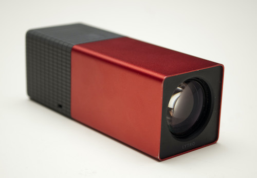 Lytro Camera from Lytro, a startup founded by Ren Ng. |
 Actual Lytro camera sample taken by me. |
As discussed previously, the magic of this camera comes from the array of microlenses located in front of the sensor. Each microlens forms a tiny sharp image of the lens aperture, measuring the directional distribution of light at that microlens (Ng). However, plenoptic cameras have their problems and challenges. For example, correlating the size of the microlenses and the pixels of the matrix which lies beneath, the distance between the microlenses and the matrix, and all other parameters combined makes it really difficult to get well focused, high-resolution pictures under each microlens at the same time. The math behind microlensing it is particularly complicated, for more information you can read Ren Ng’s paper on Light Field Photography here.
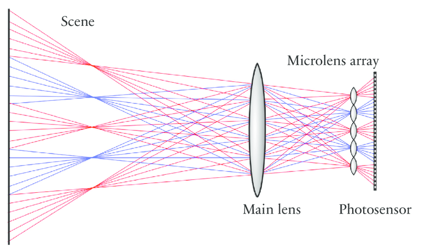 Microlenses in front of camera sensor. |
For this project, we will explore and work with light field data obtained by the Stanford Light Field Camera array, which is an array of cameras places in a grid. This array gave origin to the microlensing idea, which as we saw, can be considered as an array of tiny cameras the main camera. We will use the light field data from the Stanford’s Computer Graphics Laboratory to recreate depth refocusing and aperture adjustments and effectively simulate a real camera with multiple lens configurations.
PART 1: Depth Refocusing
The most appealing application of captured light fields is that we can refocus on any object post-facto. In this section, we will work with light fields containing 290 images arranged in a 17 x 17 grid, captured over a plane orthogonal to the optical axis of the Stanford’s Computer Graphics Laboratory’s camera array. Every image captures a different view from the same scene, and every pair forms a stereoscopic view where closer objects to the camera array appear to have a greater lateral shift compared to object farther behind. This effect can be appreciated by taking a sample of the leftmost and rightmost images from a grid row:
 Stereoscopic view were we can appreciate the sideway displacement of near and far objects. |
These shift differences between closer and father objects enable achieving complex effects such as depth refocusing and aperture adjustment using simple image manipulations such as shifting and averaging. The shift can be calculates using the information embedded on every filename. Every filename follows a format: out_y_x_v_u_.png where (x, y) represents the coordinates within the 17 x 17 image grid and (u, v) represent the actual physical camera coordinates used to setup the camera array. In order to generate images refocused at different depths, we implement the following algorithm:
- Scale all camera coordinates to a range from 0.0 to 1.0
- Select the central image of the grid, in this case image at location 8 x 8 get its camera coordinates (u’, v’)
- For every image in the grid, compute the shift by subtracting its camera coordinates (u, v) from (u’, v’). In other words: (du, dv) = (u’ – u, v’ – v)
- Compute an hyperparameter value α, such that when we translate each image by (α * du, α * dv) all the images match in a local neighborhood around position (ix, iy) within the image (depth from stereo)
- Shift all images by (α * du, α * dv) and average them to get the final resulting image
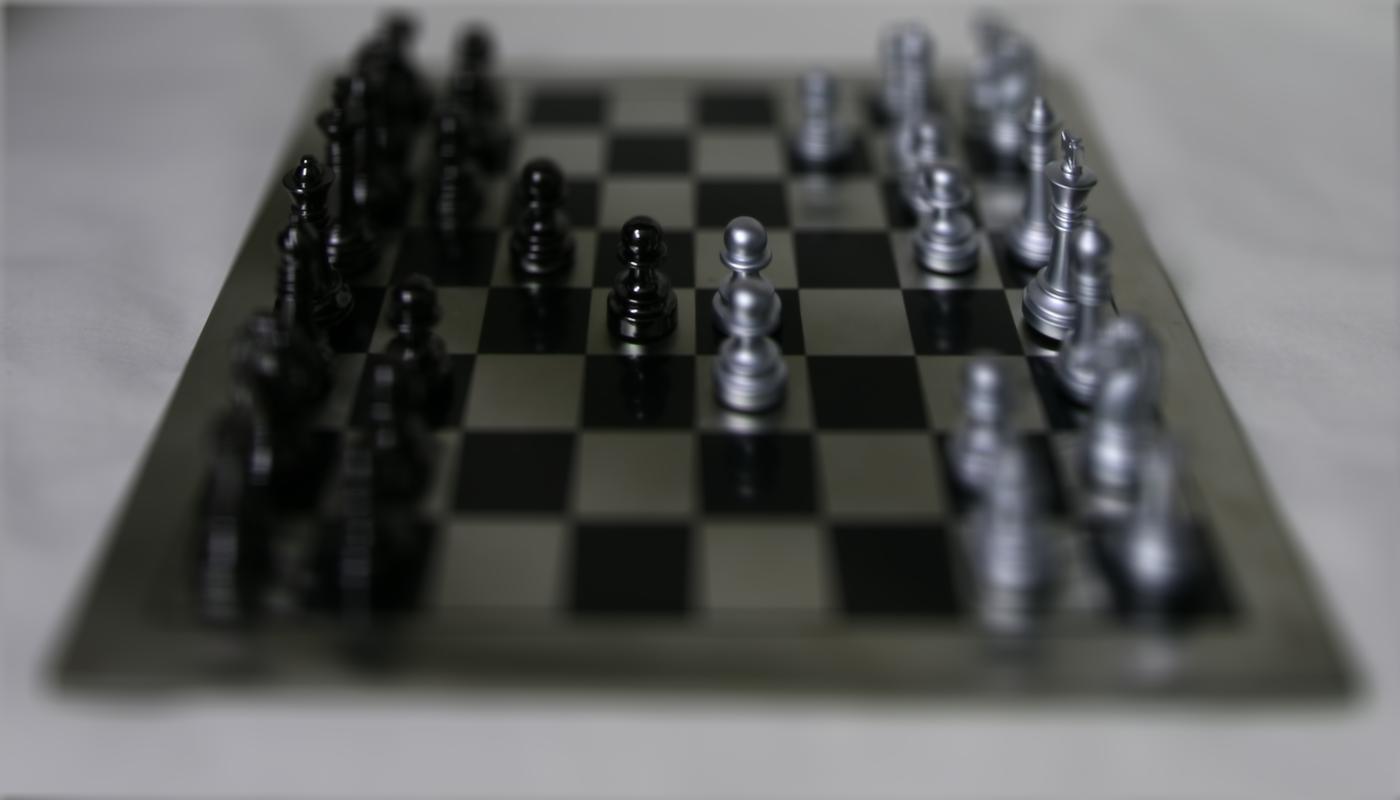
After implementing the algorithm, we can get images focused at different depths. Below we show a sample image from the light field set, two different images focused at different points, and a focus stack animation showing the depth refocus in action.
Chessboard Lighfield
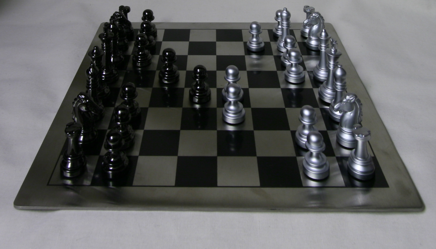 Data field sample image. |
 Depth refocusing sample. |
|
 Depth refocusing sample. |
 Depth refocusing stack. |
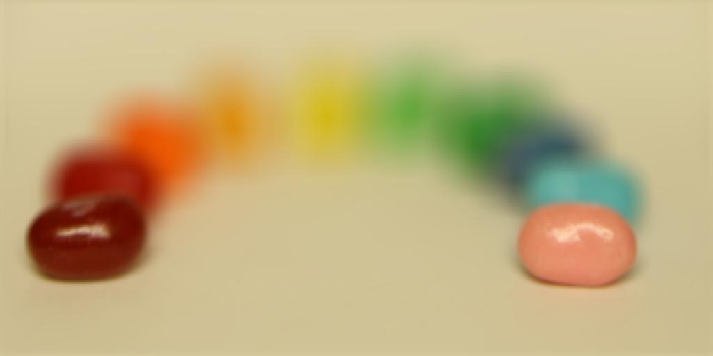
Jellybean Lighfield
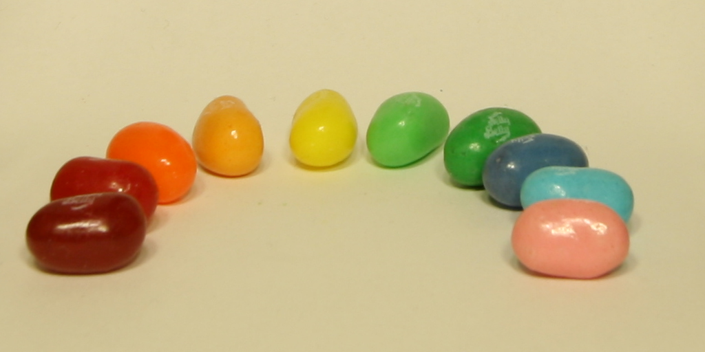 Data field sample image. |
 Depth refocusing sample. |
|
 Depth refocusing sample. |
 Depth refocusing stack. |
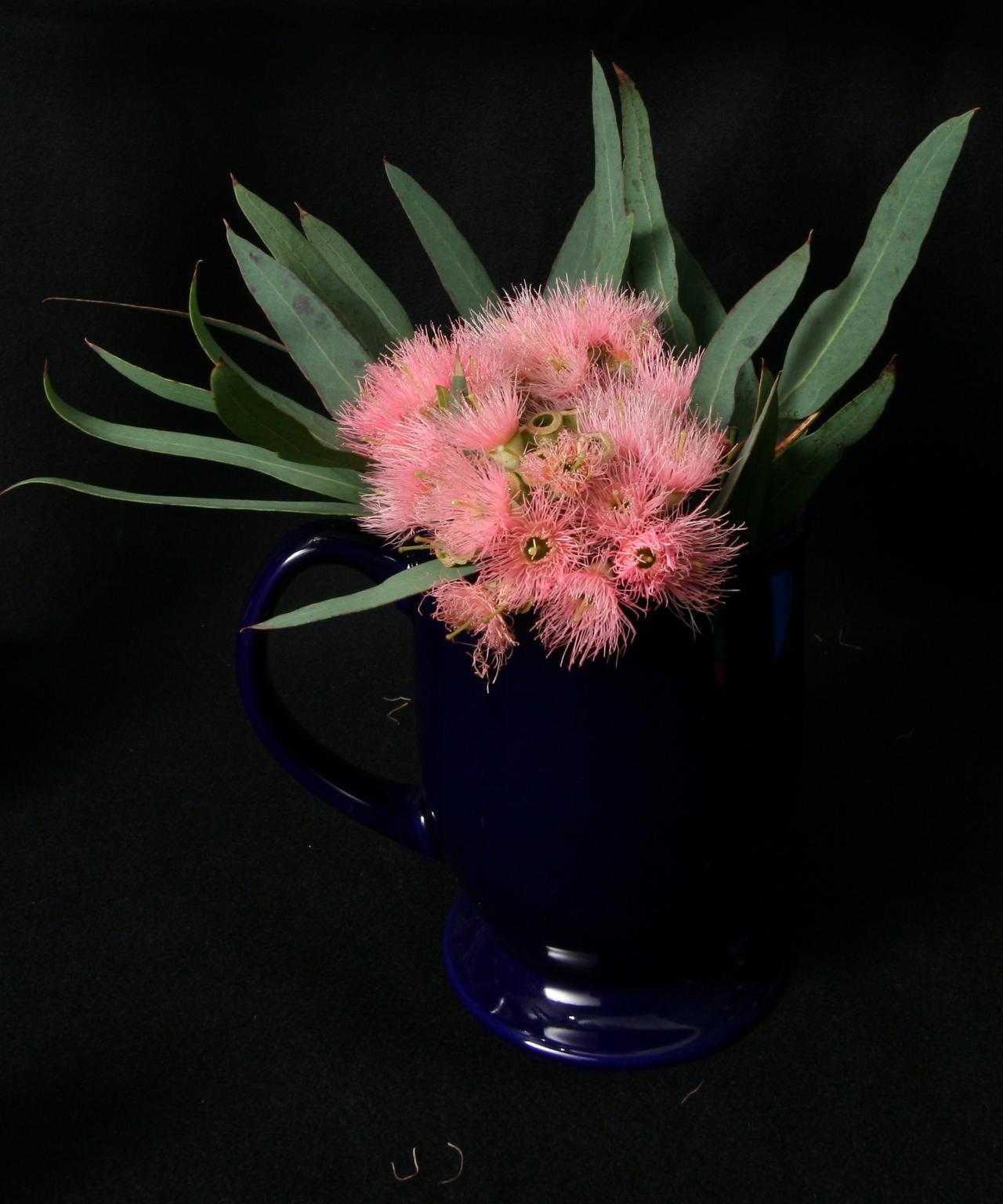
Flower Lighfield
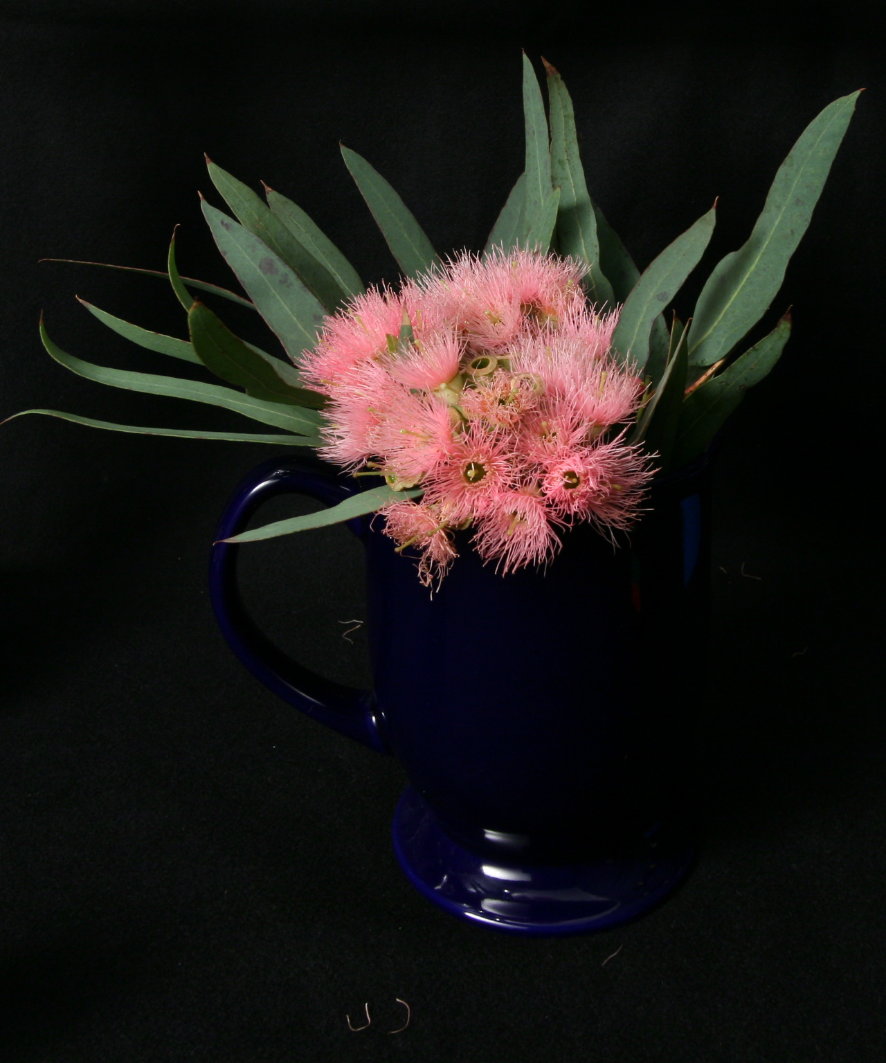 Data field sample image. |
 Depth refocusing sample. |
|
 Depth refocusing sample. |
 Depth refocusing stack. |
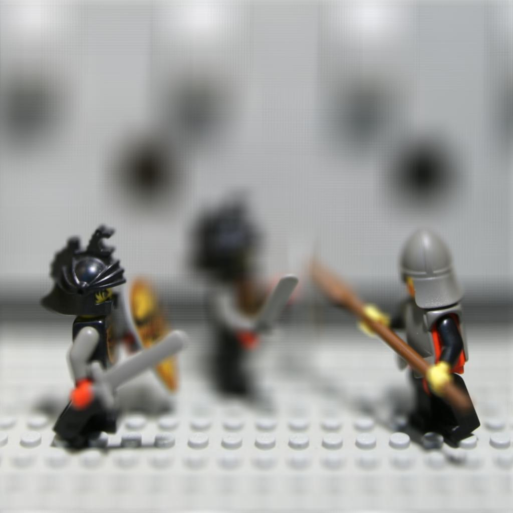
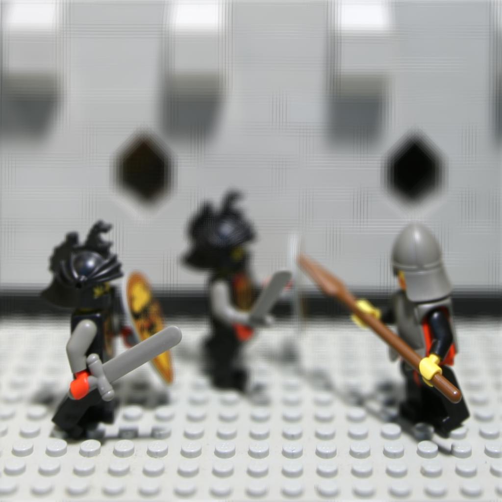
Knights Lighfield
 Data field sample image. |
 Depth refocusing sample. |
|
 Depth refocusing sample. |
 Depth refocusing stack. |
PART 2: Aperture Adjustment
In the previous section, the bokeh or blur around the shar area is essentially the result of averaging all the non-aligned areas of all images. Note that the matching (sharp area) from every stereo pair across all images is relatively small. The distance between the nearest and farthest in-focus point in an image is known as depth of field (DoF), and it is directly related to the aperture size of a lens. In this section we will simulate the aperture blades of a camera so we can adjust the aperture size so we can get more (or less) object in focus. The basic idea is relatively simple. In the previous section we averaged all images in the light field set, which produced only a very thin DoF (colloquially known as “razon blade” shallow depth of field). To increase the DoF, we need to limit the number of images to be shifted and averaged. In other words, the fewer images we combine (especially nearby images within the image grid) the less blur will be present in the final image, thus producing a wider DoF (area in focus). For this, we just take on the work done in part 1 and just add a condition to limit the number of images to be shifted and blended. We define a hyperparameter, radius, that will indicate the maximum distance between the camera coordinates from the central image (8 x 8) and the camera coordinates of any other image. In this way we can control how wide or narrow the are in focus should be. The hyperparameter α will still define the central area of focus, thus simulating a completely functional camera lens! Sample results and animations are found below.
Chessboard Lighfield
|
Data field sample image. |
 Aperture Adjustment sample. |
|
 Aperture Adjustment sample. |
 Aperture Adjustment stack. |
Jellybean Lighfield
|
Data field sample image. |
 Aperture Adjustment sample. |
|
 Aperture Adjustment sample. |
 Aperture Adjustment stack. |
Flower Lighfield
|
Data field sample image. |
 Aperture Adjustment sample. |
|
 Aperture Adjustment sample. |
 Aperture Adjustment stack. |
Knights Lighfield
|
Data field sample image. |
 Aperture Adjustment sample. |
|
 Aperture Adjustment sample. |
 Aperture Adjustment stack. |
PART 3: Lightfield Capture (Bells & Whistles)
Let us recall that a plenoptic camera captures light fields and not just 2D snapshots like our everyday cameras. Each captured light field allows us to adjust focus and aperture post facto, plus other cool applications like 3D reconstruction! (They encode lots of information about the scene). For this bells and whistles, I decided to play around and try assembling my own light field camera... well, kind of. Unlike Stanford, I don't have a fancy array with hundreds of cameras... or a lab. So, I went ahead with my trusty old Nikon and a hint of ingenuity, and voila! I got some results! Basically, I captured an 9x9 array of 81 images with close-to-millimetric accuracy using a tripod and a macro slider. Then, I rectified the images manually to remove undesired shifts (took several hours). Finally, by using my fresh knowledge on image shifting, I was more or less able to recreate Stanford's experiment. The result may not look like much, but to be honest, I am actually surprised it worked somewhat.
Setup
We setup a little scene using small object, artificial illumination, a DSLR camera, a tripod, and a macro photography slider to get and two-dimensional array of size 9 x 9 (81 images). The settings for the camera are the following: aperture f/22 (smallest aperture so everything is in focus), exposure time of 1/20 sec, 35 mm lens.
 Camera Setup |
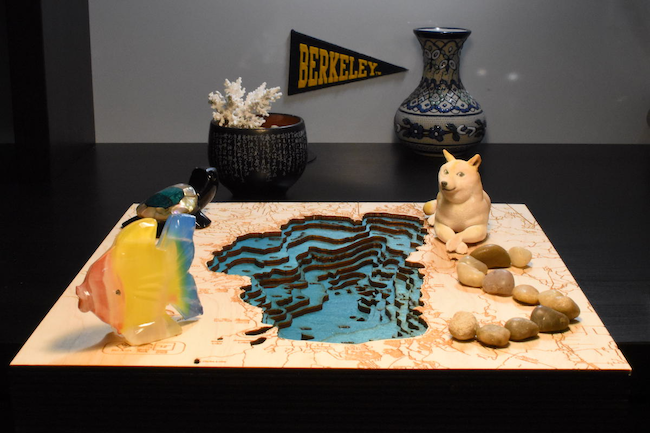 Scene to be captured |
Good Result
For this light field, every image was taken with a spacing of approximately 2.5mm. The resulting light field can be interactively visualized below using a little visualizer I made in JavaScript.

The results for depth refocusing and aperture adjustment are shown below. The refocusing adjustment is not good, while the aperture adjustment is decent.
 Depth refocusing sample. |
 Aperture Adjustment stack. |
Failure Case
Next, I tried to capture a table with soda cans and flowerpots, but results were very blurry as shown below.
 Depth refocusing sample. |
The resulting light field was probably way too unbalanced given that my room does not have hard floor (carpet), so the tripod setup moved between each capture adjustment. This very probably caused a non-aligned, light field capture. Let us remember that researchers at Stanford had a precise, custom-made, camera grids, plus they meticulously calibrated the cameras to sub-millimetric precision. Still, trying to replicate the experiment was fun!
Final thoughts
The human ambition to capture light has achieved a cornerstone by the different ways and techniques to capture and visualize light fields. The flexibility that they provide promise will be revolutionary in different areas of research and even in the artistic field. Capturing high-resolution light field is still a technical challenge, but current advancements in optics may change that sooner that we expect!